Driving Power MOSFETs Without Shoot-Through
Electrical Diagrams · made in Skemio
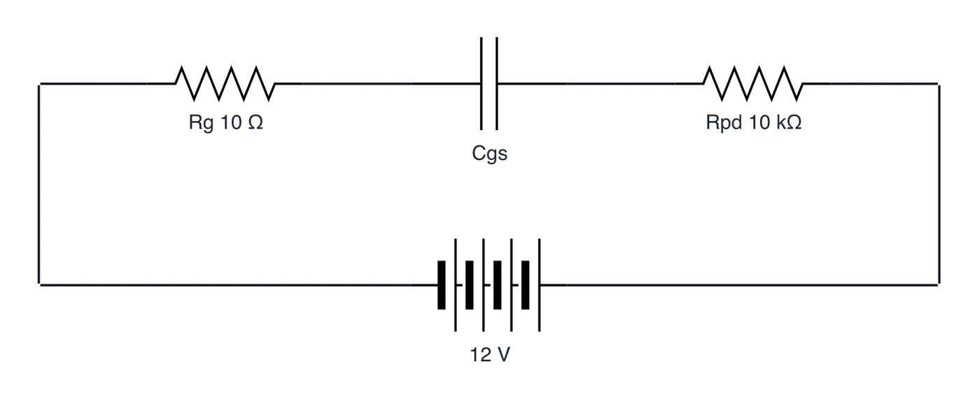
What it shows
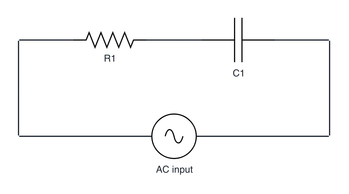
- Internal gate-source capacitance (Cgs) acts like a short during switching transitions.
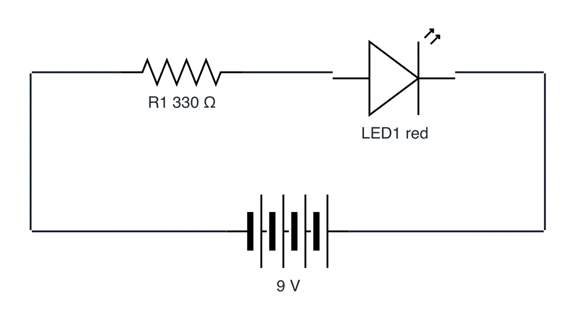
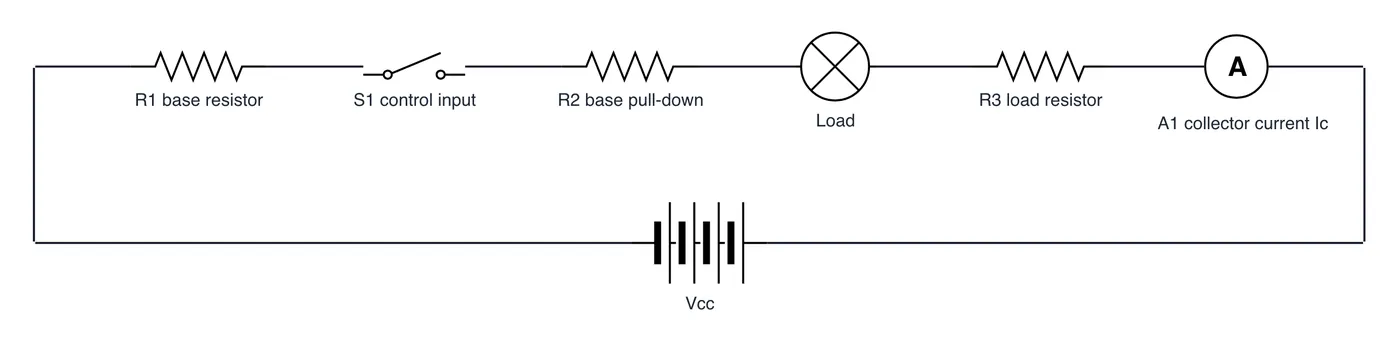
- A series gate resistor dampens high-frequency ringing and limits drive peak current.
- A gate-to-source pull-down resistor prevents unintended turn-on when the MCU boots.
The takeaway
Treat the MOSFET gate as a capacitor: use a series resistor to stop ringing and a pull-down to prevent floating states.
- #MOSFET
- #PowerElectronics
- #CircuitDesign
- #Hardware
- #Electronics