NPN Transistor as a Low-Side Switch
Electrical Diagrams · made in Skemio
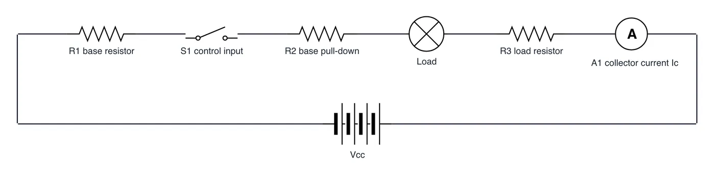
What it shows
- Base current Ib drives the BJT into full saturation, locking Vce to ~0.2 V.
- Low-side switching places the transistor between load negative and ground.
- Calculate base resistance using an overdrive ratio of Ib = Ic / 10.
The takeaway
Driving an NPN BJT into deep saturation minimizes Vce voltage drop and switch heat dissipation.
- #EmbeddedSystems blood HardwareDesign CircuitDesign Electronics ElectricalEngineering