Passive RC Low-Pass Filter Circuit
Electrical Diagrams · made in Skemio
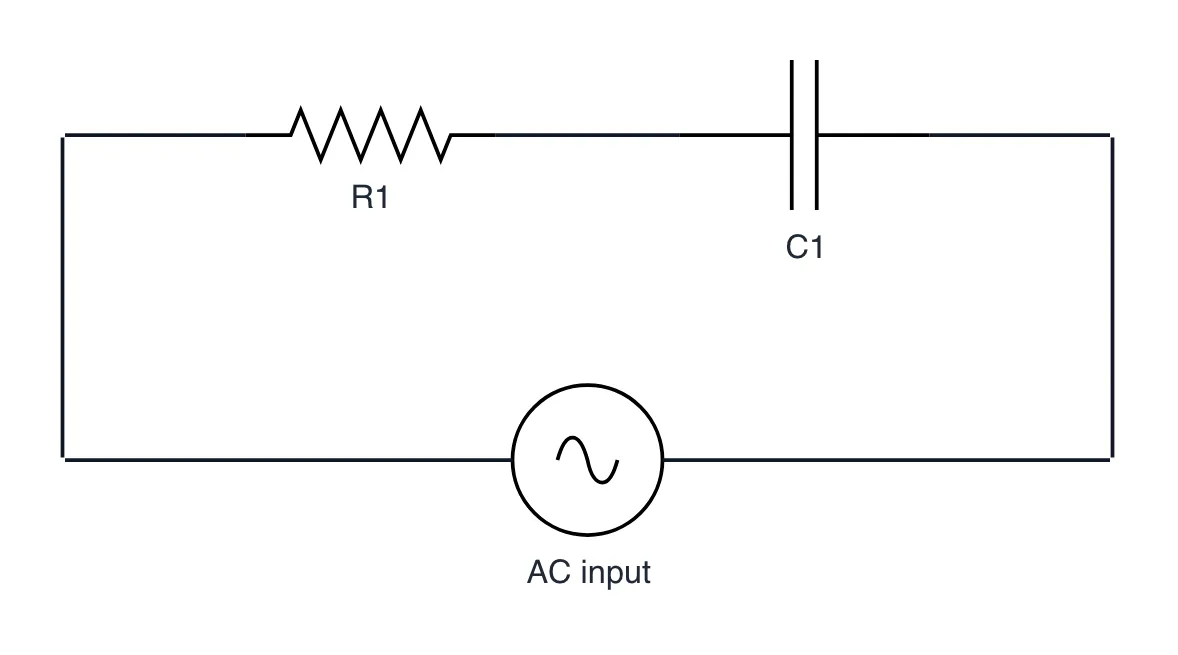
What it shows
- Capacitive reactance Xc = 1 / (2πfC) drops inversely with signal frequency.
- Cutoff frequency fc = 1 / (2πRC) marks the -3 dB attenuation corner point.
- Signals beyond cutoff roll off at a steady -20 dB per decade slope.
The takeaway
An RC low-pass filter passes DC while smoothly shunting high-frequency signal noise to ground.
- #SignalProcessing blood Electronics CircuitDesign Hardware ElectricalEngineering