Inside a Variable Frequency Drive (VFD)
Electrical Diagrams · made in Skemio
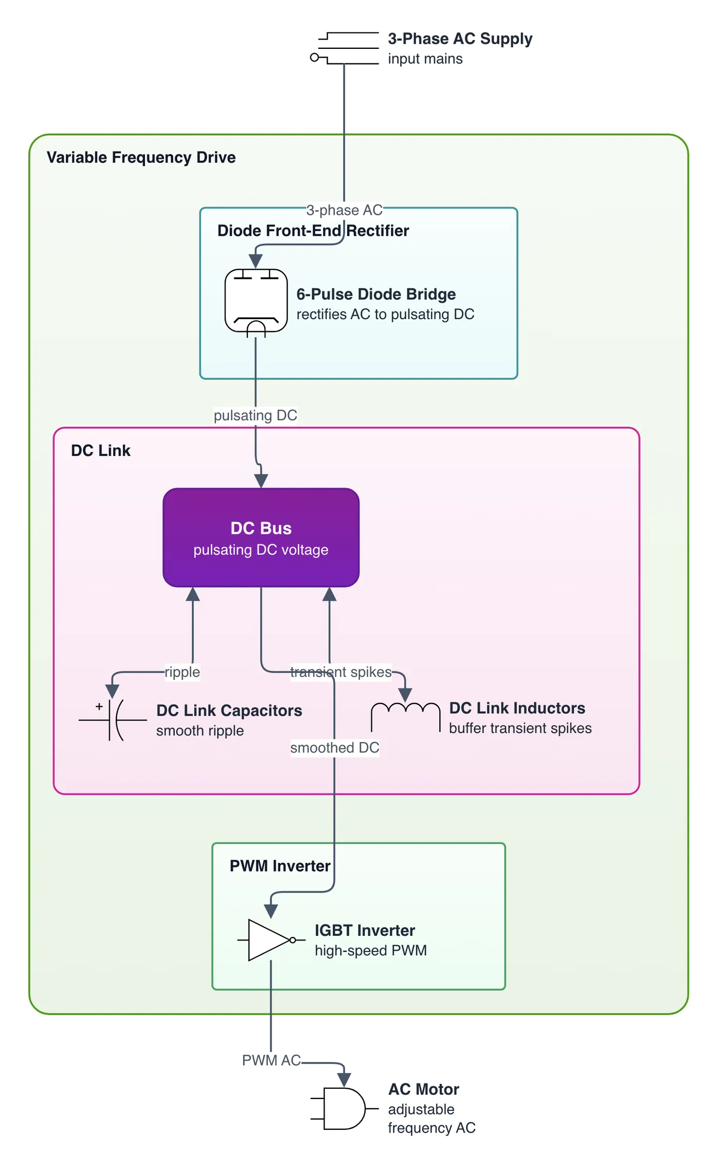
What it shows
- 6-pulse diode bridges rectify 3-phase AC into pulsating DC voltage.
- DC link capacitors and inductors smooth ripple and buffer transient spikes.
- IGBT inverters use high-speed PWM to synthesize adjustable frequency AC.
The takeaway
VFDs decouple input and output frequency through a DC intermediate link, enabling precise motor torque.
- #VFD
- #PowerElectronics
- #IndustrialAutomation
- #ElectricalEngineering
- #ElectricMotors
- #Motors