Inverting Op-Amp: Gain and Virtual Ground
Electrical Diagrams · made in Skemio
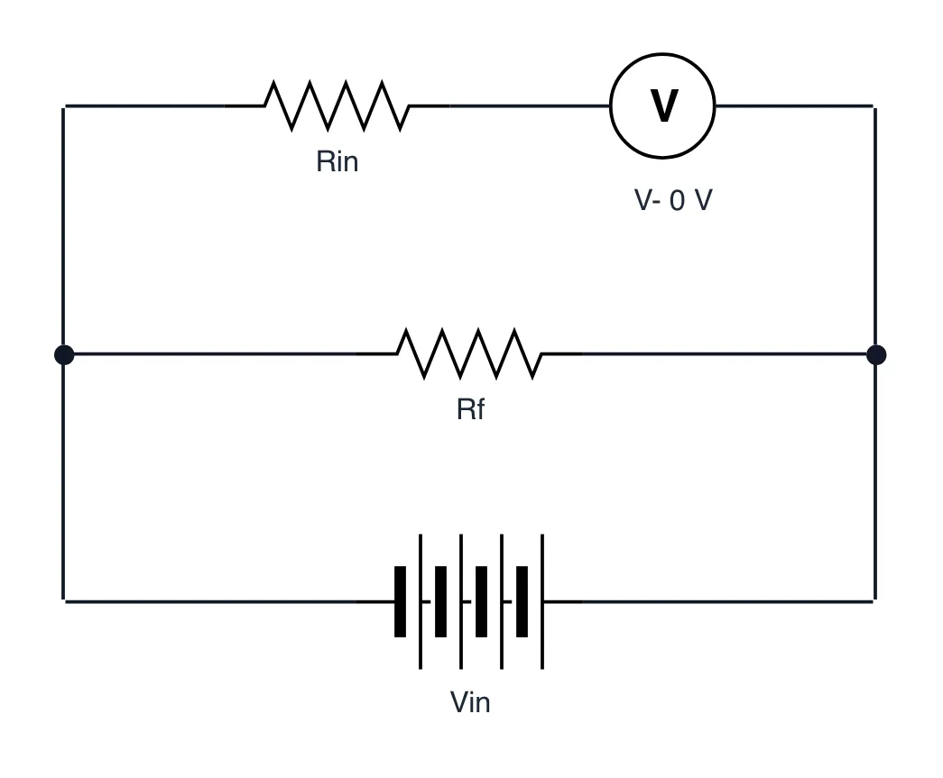
What it shows
- Gain is set precisely by ratio -Rf/Rin, independent of internal open-loop gain.
- Inverting pin sits at a virtual ground (0V) because negative feedback drives it.
- Input impedance equals Rin, so avoid small Rin to prevent loading your signal.
The takeaway
Negative feedback forces the summing junction to virtual ground, making closed-loop gain rely purely on two resistors.
- #Electronics
- #CircuitDesign
- #OpAmp
- #ElectricalEngineering
- #Hardware