Pull-Up vs Pull-Down Digital Inputs
Electrical Diagrams · made in Skemio
What it shows
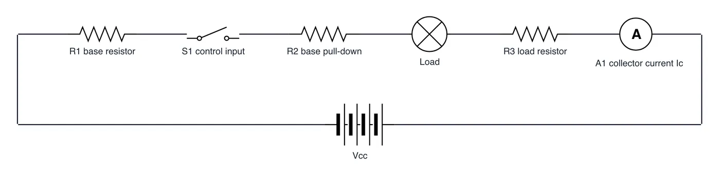
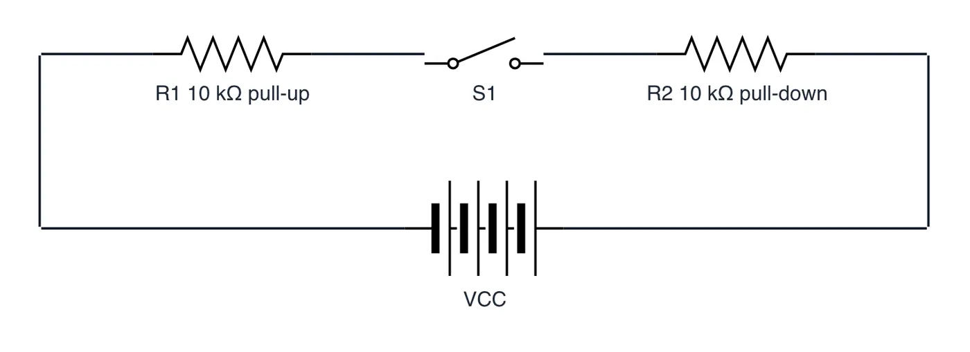
- A pull-up resistor ties the input pin to VCC, making LOW the active state.
- A pull-down resistor ties the pin to GND, making HIGH the active state.
- Typical 10 kΩ values limit current to 0.5 mA while sinking ambient noise.
The takeaway
Pull resistors define a deterministic default voltage so high-impedance inputs never float randomly.
- #EmbeddedSystems
- #Electronics
- #Microcontrollers
- #HardwareDesign
- #Arduino
- #Circuits