Passive RC High-Pass Filter Fundamentals
Electrical Diagrams · made in Skemio
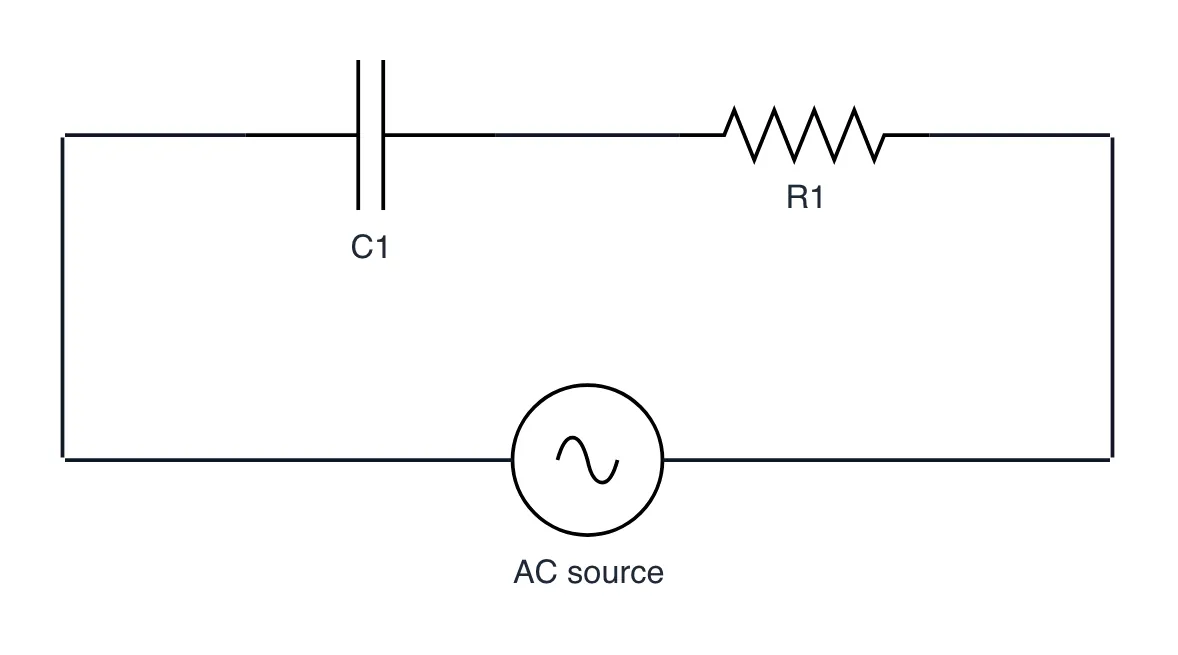
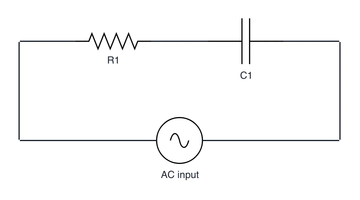
What it shows
- Capacitive reactance Xc is inversely proportional to frequency (1 / 2*pi*f*C).
- Cutoff frequency fc = 1 / (2*pi*R*C) marks the -3dB power point and 45-degree phase lead.
- Blocks DC bias completely while acting as a frequency-dependent voltage divider.
The takeaway
An RC high-pass filter strips DC bias by placing high capacitive reactance at low frequencies and passing AC through R.
- #Electronics
- #SignalProcessing
- #Filters
- #Circuits
- #ElectricalEngineering