Protecting MCUs with Optocoupler Isolation
Electrical Diagrams · made in Skemio
What it shows
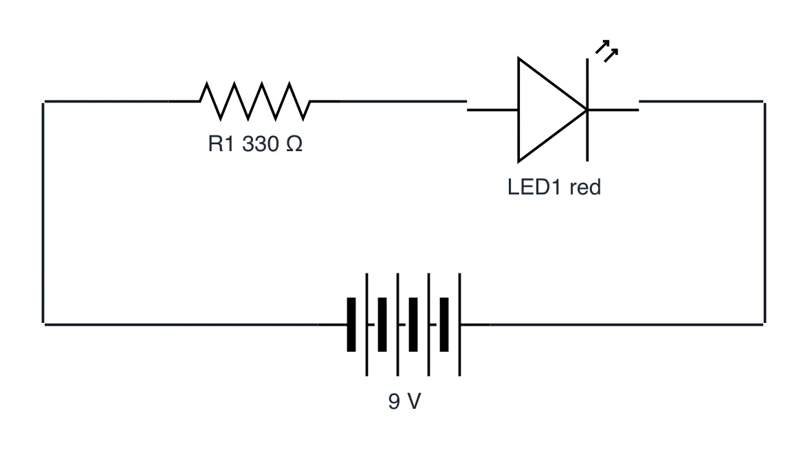
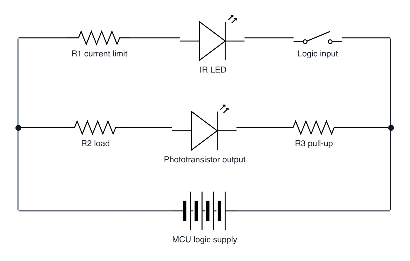
- Internal IR LED converts electrical logic into optical photons.
- Total galvanic isolation eliminates noisy shared ground loops.
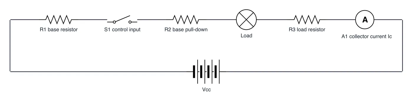
- Phototransistor switches isolated secondary rails safely.
The takeaway
Galvanic isolation trades physical electrical contact for light, safeguarding sensitive logic chips.
- #EmbeddedSystems
- #Electronics
- #HardwareEngineering
- #PCBDesign
- #CircuitDesign
- #Engineering