Split-Phase 120V/240V Residential Panel
Electrical Diagrams · made in Skemio
What it shows
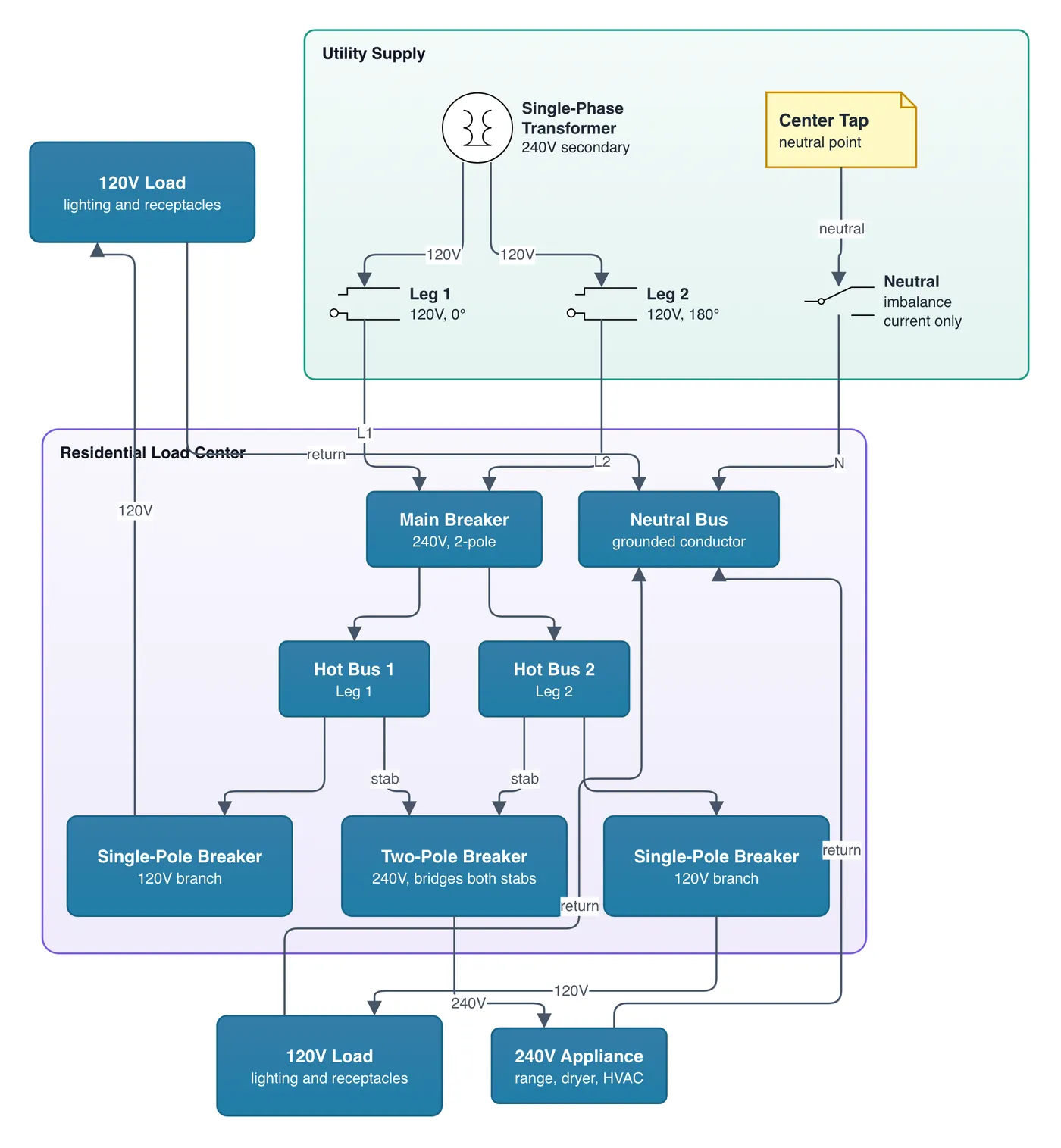
- A single-phase 240V secondary with a center tap creates two 120V legs 180° apart
- Neutral carries only the imbalance current between Leg 1 and Leg 2
- Two-pole breakers bridge both hot bus stabs to power heavy 240V loads
The takeaway
Split-phase power supplies low-voltage wall outlets and high-power appliances from one center-tapped transformer.
- #ElectricalDistribution
- #Electrician
- #SplitPhase
- #PowerEngineering
- #CircuitDesign
- #HomeElectrical