Wind Turbine Electrical Conversion Chain
Electrical Diagrams · made in Skemio
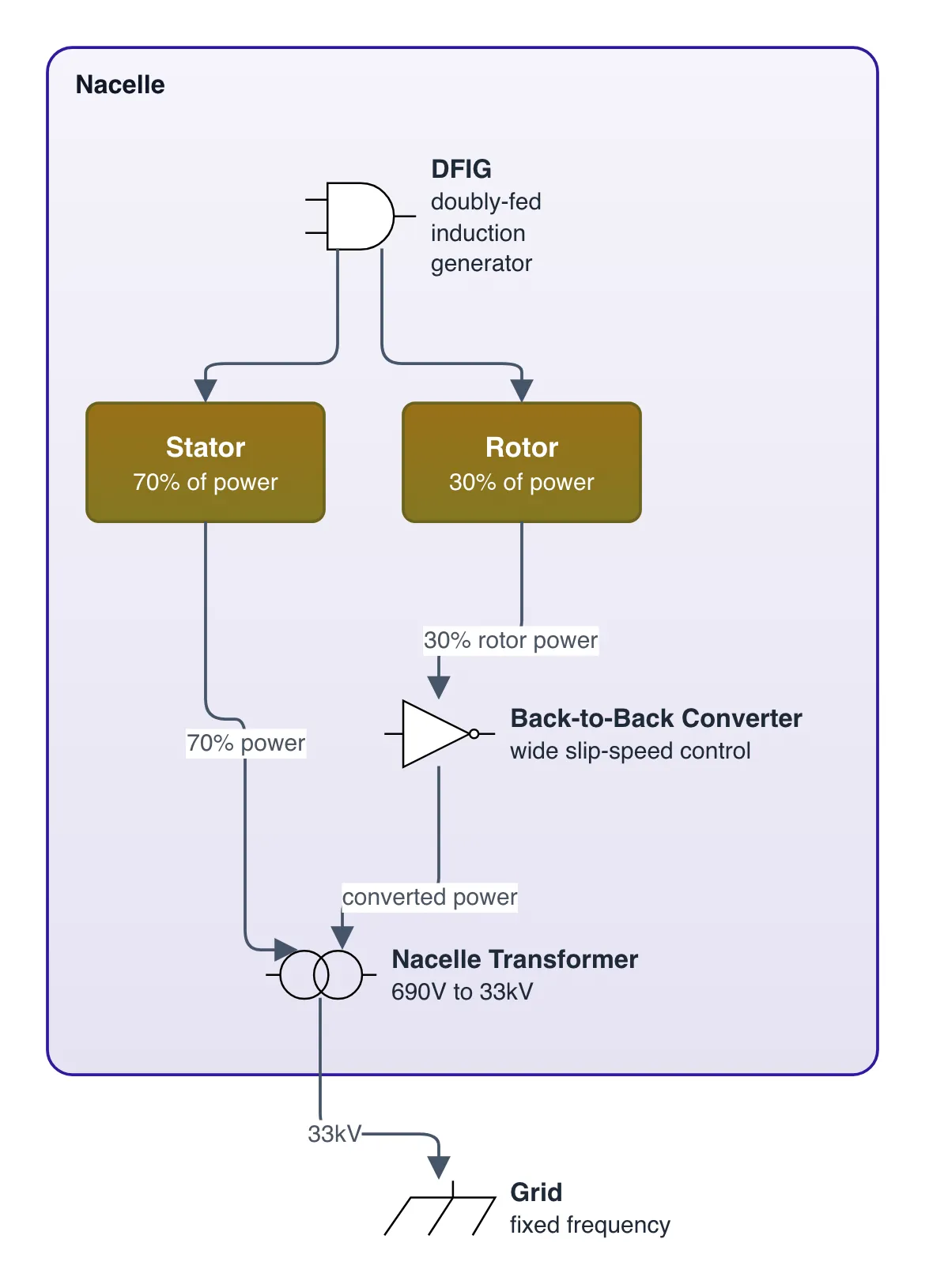
What it shows
- DFIG sends 70% of power straight from stator to grid at fixed frequency.
- Back-to-back converter handles 30% rotor power for wide slip-speed control.
- Nacelle transformer steps 690V generation up to 33kV to cut collector losses.
The takeaway
DFIG designs downsize costly power electronics to roughly 30% while maintaining variable turbine speed.
- #WindEnergy
- #DFIG
- #RenewableEnergy
- #PowerElectronics
- #EnergyGrid