Zener Diode Voltage Regulator Circuit
Electrical Diagrams · made in Skemio
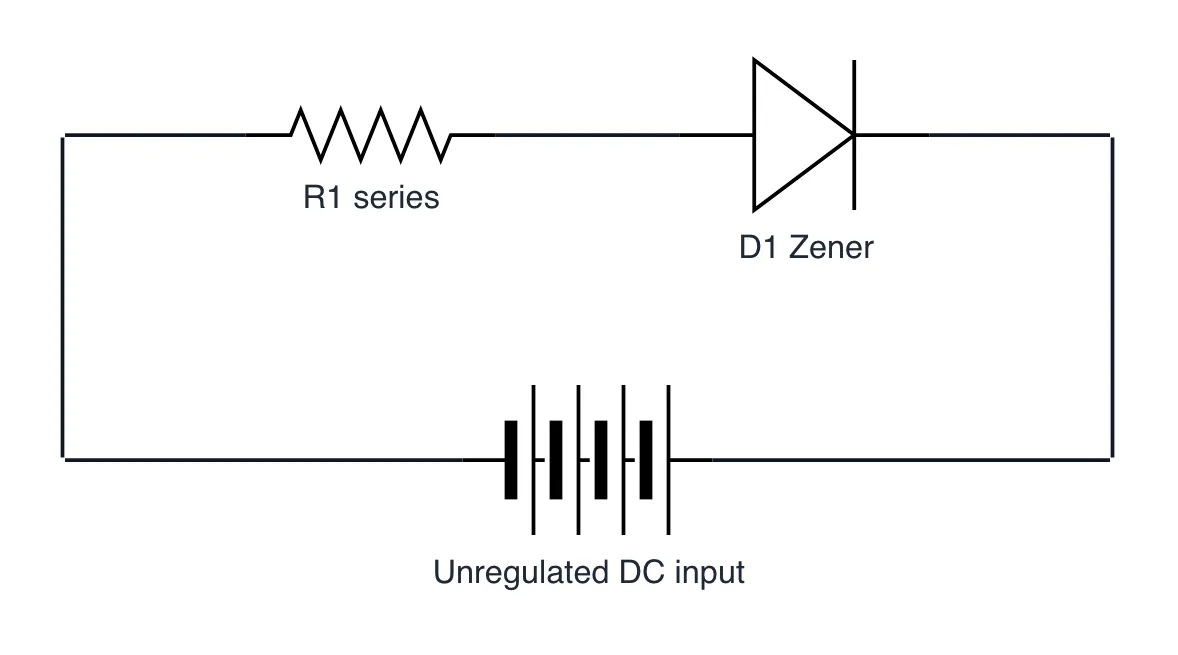
What it shows
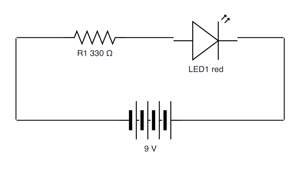
- Zeners enter controlled avalanche breakdown at a precise reverse voltage.
- A series resistor drops excess voltage and limits Zener shunt current.
- Output voltage remains fixed even if the unregulated input fluctuates.
The takeaway
Zener shunt regulators maintain a constant voltage by absorbing supply spikes in reverse breakdown mode.
- #Electronics
- #HardwareDesign
- #AnalogElectronics
- #ElectricalEngineering
- #Circuits
- #Semiconductors